When you want to know what is inside something, the usual answer has always been to cut it: embed it in resin, polish the face, put it under a microscope. You get one beautiful cross-section and you lose the sample for good. And if the cut lands two or three millimetres off, the thing you wanted to see may not be in that face at all — so you find another sample and start again.
It gets worse the moment the sample cannot be cut at all — a failed part that has to go back to the customer, a fossil or an artefact, a one-of-a-kind biological specimen, an expensive board where you need to see the solder joints inside but still have to use it afterwards. For these, cutting is simply a dead end.
How CT works
It starts by firing X-rays through the object and measuring how much each part of the beam is absorbed. What comes out is a single two-dimensional shadow — which still cannot tell you how deep the dense bit sits, because every layer is stacked on top of every other in that one image.
Then the sample is rotated a fraction of a degree and shot again, and again, until there are hundreds or thousands of shadows from all around it. Software then works backwards to figure out what density at every point in the volume would produce exactly that set of shadows. That step is called reconstruction, and what it yields is a three-dimensional model holding a density value at every point.
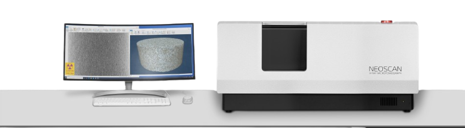
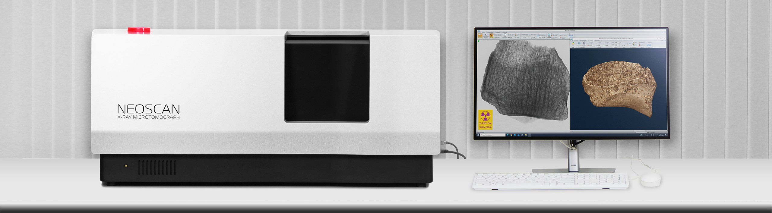
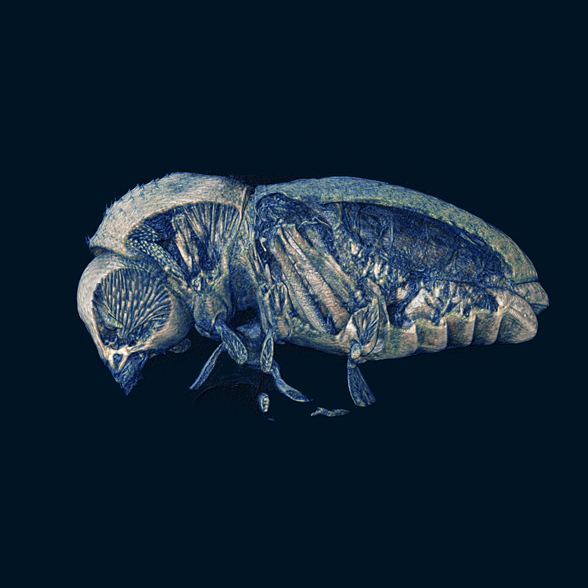
Once that model exists, the dissection happens on screen instead. You can step through slices, cut on any oblique plane, or spin the internal geometry around in three dimensions — as many times as you like, because the real sample is still intact on the bench.
Voxel size and resolution are not the same number
This is where CT spec comparisons most often go wrong. Datasheets like to lead with the smallest voxel size, but a voxel is the size of one cube in the reconstructed data — not the size of the smallest detail the machine can actually separate. The two can differ by a wide margin.
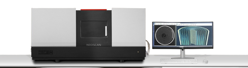
The clearest example sits in NEOSCAN’s own flagship. The N90 reaches a voxel size of 40 nm, while its spatial resolution measured on the standard JIMA pattern is 300 nm — nearly eight times apart. Both numbers are correct and they do not contradict each other; they simply measure different things.
What actually sets resolution is a combination of physical factors: the focal spot of the X-ray source, where smaller means sharper edges; the geometric magnification set by the distances between source, sample, and detector; the quality of the detector itself; and how still the whole system stays for the duration of the scan. If the sample shifts or the system drifts while thousands of projections are collected, sharpness disappears while the voxel figure stays exactly the same.
The question to ask when comparing
Do not stop at the smallest voxel. Ask what the spatial resolution measures, by what method, and against which standard pattern. A manufacturer that quotes a JIMA figure is one willing to be compared on common ground; a spec sheet offering only a voxel number has not finished answering the question.
Choosing by sample size and the detail you need
| Model | Resolution / voxel | Max sample | Notable |
|---|---|---|---|
| N60 | 8 µm / 3.8 µm voxel | Small samples | Most compact, USB3 connected, source to 65 kV |
| N70 | Under 4 µm / 2.5 µm voxel | 100 × 220 mm | 7MP flat-panel detector for everyday 3D work |
| N80 | 2 µm / submicron voxel | 100 × 200 mm | Source to 110 kV, with phase contrast retrieval |
| N90 | 300 nm on JIMA / 40 nm voxel | Very small samples | World’s first benchtop nano-CT, dual detector, integrated micro-XRF |
| NXL | For large parts | 320 × 540 mm | Source to 150 kV / 75 W with a long-life detector |
The reason for that trade-off is magnification. Seeing finer detail means moving the sample closer to the source so its shadow spreads further across the detector — but the closer it sits, the less of it the beam covers. So choosing a system starts with how big the real samples are, and only then with how fine you need to see.
Integrated micro-XRF: knowing which element it is
CT tells you where the dense regions are and what shape they take, but not what they are made of. A bright spot might be iron, or lead, or a different mineral that happens to sit at a similar density. The N90 therefore carries a micro-XRF module in the same cabinet: it excites the sample so each element emits its own characteristic radiation, reads which elements those are, and maps their distribution over the geometry — without unmounting the sample or realigning anything.
Where it gets used
- Geology and petroleum — pore structure and how the voids connect, to judge fluid flow. A single cut face can never answer that.
- Materials and additive manufacturing — porosity, lack-of-fusion defects, and fibre distribution in composites, which decide where a part will fail.
- Bone and dental — measuring density and trabecular architecture in three dimensions, for research and for evaluating implants.
- Electronics — solder joints under a BGA, cracks in vias, and package stack-up, with the board still usable afterwards.
- Fossils, archaeology, and biological specimens — the cases where the sample is unique and cutting is out of the question.
Limits worth knowing first
- Thick, dense material such as a solid metal block absorbs the beam until the data runs out. Source voltage has to match the material and its thickness.
- The sample must stay perfectly still throughout. Anything that dries, shrinks, or has liquid moving inside will blur the reconstruction.
- High-resolution scans take hours, not minutes. This is not a tool for high-volume inline inspection.
- The datasets are large. Plan the workstation and storage up front rather than discovering the problem later.
NEOSCAN was founded by Alexander Sasov, who pioneered benchtop micro-CT from its earliest days. What separates these systems from room-sized industrial CT is the intent that an ordinary lab can own one: it sits on a bench, one software package carries you from acquisition to 3D rendering, and updates are free. If you are weighing up which model suits the samples you actually have, the figures worth bringing to the conversation are real sample size, the smallest detail you must resolve, and the material being scanned.